112/5 Shelves
Search This Category
Patent Model
Name/Title
Patent Model
Lexicon
Description
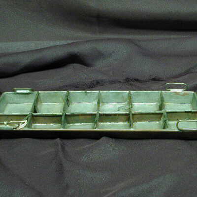
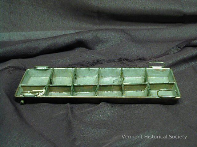
Patent model of an evaporator. The model consists of a tinned copper tray separated into 12 compartments. The center divider lists to the side, creating unequal compartments. There are four oval wire handles on the long sides near the corners.
Use
From 1790 to 1880, the US Patent Office required a three-dimensional working model to demonstrate each new invention.
Acquisition
Accession
1946.31
Relationships
Related Places
Place
Perkinsville
Village
Weathersfield
Town
Windsor County
County
Vermont
State/Province
United States of America
Country
North America
Made/Created
Artist Information
Tolles, A.
Artist
Date made
1870
Dimensions
Dimension Description
Overall
Materials
Material
Metal, Copper, Tin
Entry/Object ID
1946.31.4
Context
Model for patent number 98,816, issued to Abner Tolles of Perkinsville, Vermont, on January 11, 1870
Label from an exhibit: "Model of an apparatus for evaporating saccharin and other solutions. Abner Tolles and Almon Durkee Tolles. Weathersfield and Royalton. 1870
Abner Tolles was born in Weathersfield on July 30, 1823, and died May 27, 1880. Almon was his nephew. The Tolleses' invention allowed for a continuous evaporation of sap, prevented back flow, and kept scum and foreign matter in the first compartment as the refined liquid moved from one compartment to the next."
Patent Model
Name/Title
Patent Model
Lexicon
Description
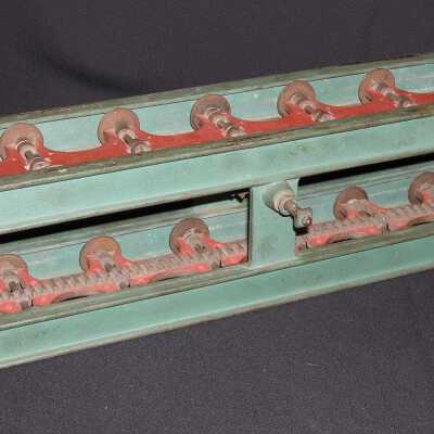
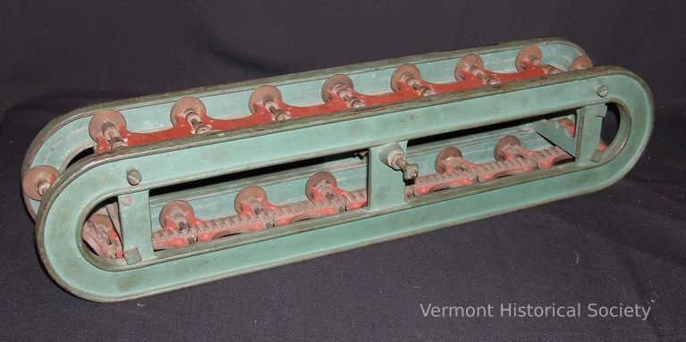
Patent model of a horse-powered machine. The model consists of two green metal ovals connects in the middle with three green metal brackets. A red metal track sits in grooves along the inside of the U-shaped pieces, creating a continuous loop.
Use
From 1790 to 1880, the US Patent Office required a three-dimensional working model to demonstrate each new invention.
Acquisition
Accession
1946.31
Relationships
Related Person or Organization
A. W. Gray & Sons
Person or Organization
Related Places
Place
Middletown Springs
Town
Rutland County
County
Vermont
State/Province
United States of America
Country
North America
Made/Created
Date made
1842
Dimensions
Dimension Description
Overall
Materials
Material
Metal
Entry/Object ID
1946.31.2
Context
For patent number 2.83B, issued to A. W. Gray on October 26, 1842. Gray was a manufacturer of farm machinery in Middletown Springs, Vermont.
Patent Model
Name/Title
Patent Model
Lexicon
Description
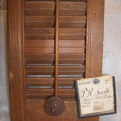
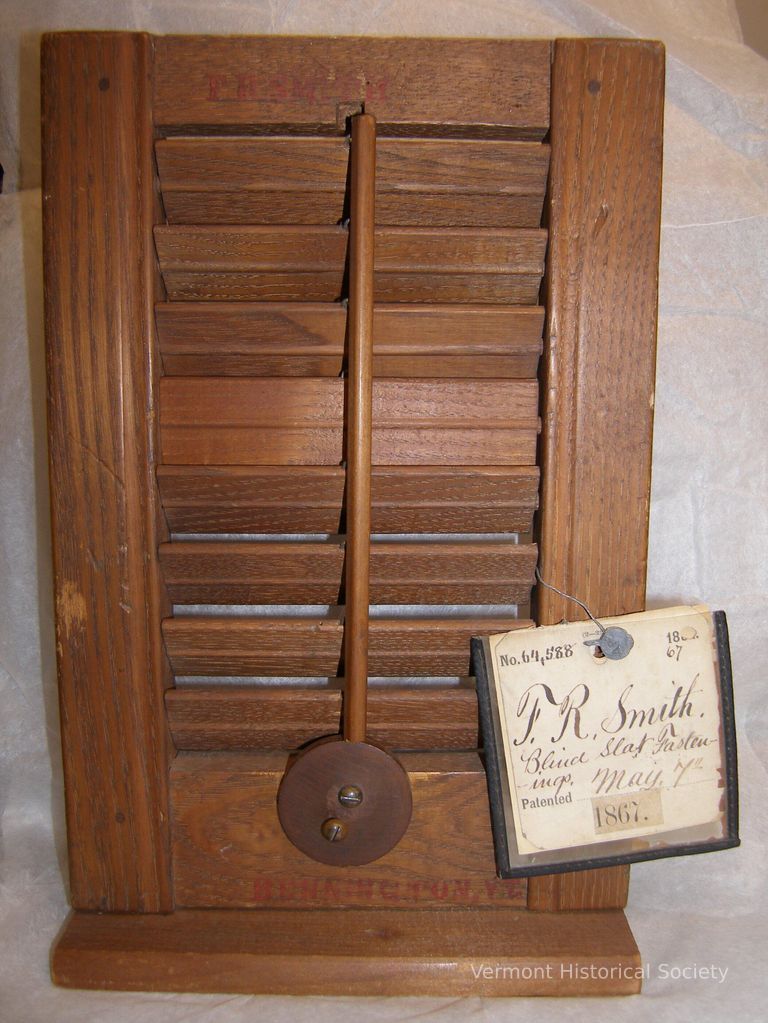
Patent model of wooden window shutters. The miniature shutter sits on a rectangular wooden base, and the blinds open and close with a vertical wooden dowel attached to wire eyes at the center of each blind. The bottom of the dowel is attached to a metal disk that rotates as the dowel is moved. A paper tag in a metal frame is attached to the model with a wire and reads, "No. 64,588 F. R. Smith. Blind Slat Fastenings. Patented May, 7th 1867." The name "F. R. Smith" is painted in red at the top of the shutter, and "BENNINGTON, VT." is painted at the bottom.
Use
From 1790 to 1880, the US Patent Office required a three-dimensional working model to demonstrate each new invention.
Acquisition
Accession
1946.31
Relationships
Related Person or Organization
Smith, F. R.
Person or Organization
Related Places
Place
Bennington
City
Bennington County
County
Vermont
State/Province
United States of America
Country
North America
Made/Created
Date made
1867
Materials
Material
Wood, Metal
Entry/Object ID
1946.31.5
Context
For patent number 64,588 issued to F. R. Smith of Bennington, Vermont
Patent Model
Name/Title
Patent Model
Lexicon
Description
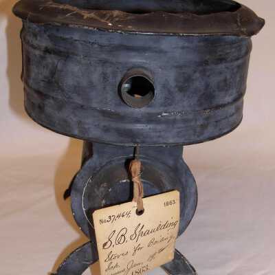
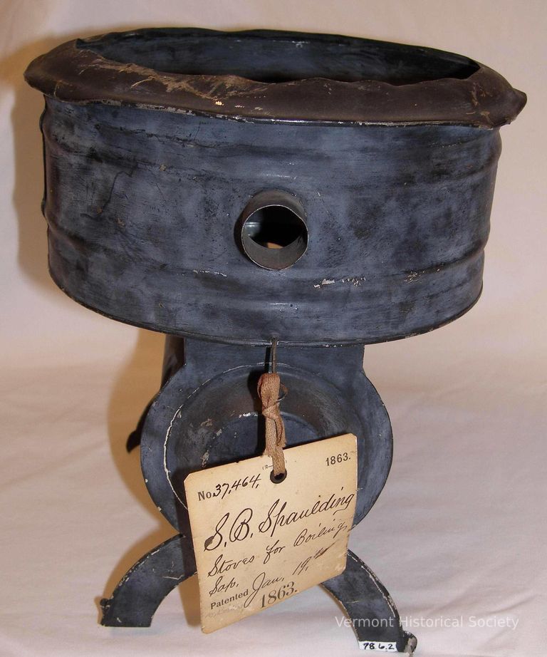
Sap boiling stove patent model. The sheet-iron boiler is composed of two main parts: a circular drum and a cylinder resting sideways underneath. The circular drum has an open top that shows iron guides to direct liquids into a trough, and a small overhang of curved iron. A single circular spout is cut into the middle band of the drum. An old paper label is attached to the side of the drum and reads, “Samual B. Spaulding / Brandon Vt.” in faded brown script. The cylinder underneath the drum has a hinged door that opens. The entire model stands on two pairs of arched legs. A hook extends off of the drum, holding a string and tag that says, “No. 37, 464 / 1863. / S.B. Spaulding / Stoves for Boiling / Sap. / Patented Jan. 19th, / 1863.” in typed and handwritten text.
Acquisition
Accession
1978.6
Made/Created
Artist Information
Spaulding, Samuel B. (1789-1878)
Artist
Date made
1863
Dimensions
Entry/Object ID
1978.6.2
Context
Invented by Samuel B. Spaulding.
Patent Model
Name/Title
Patent Model
Lexicon
Description
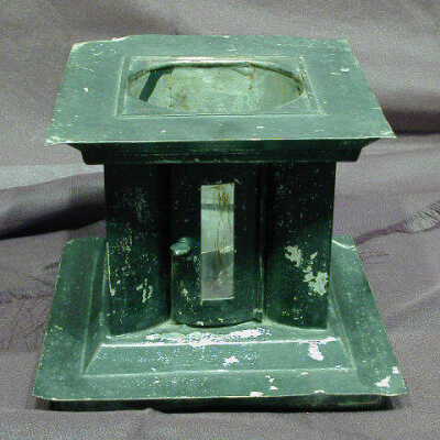
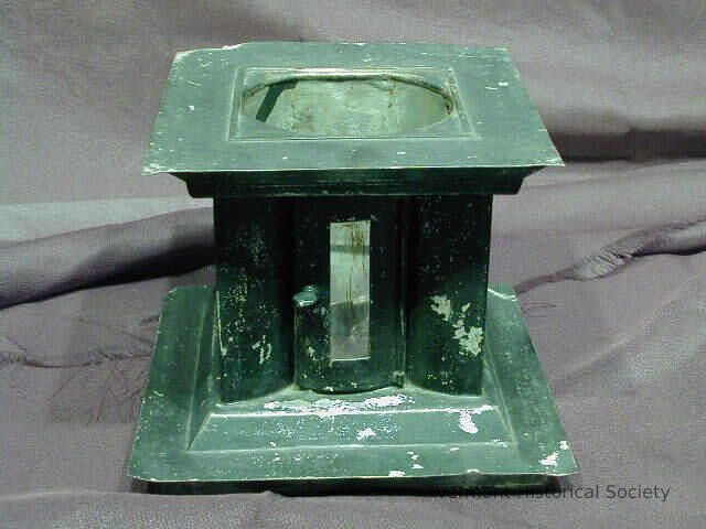
A portion of the patent model 3.876, a heating stove invented by H. Stanley on January 4, 1845. Box-like with 3.13" diameter opening (not perfect circle) on top. On one end is a 1.69" hole, probably for a pipe. On opposite side is a door with a mica window. The other two sides each have a mica window. See Worksheet.
Acquisition
Accession
1981.4
Made/Created
Date made
1845
Manufacturer
H. Stanley
Dimensions
Materials
Material
Tin
Entry/Object ID
1981.4
Patent Model
Name/Title
Patent Model
Lexicon
Description
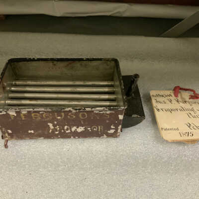
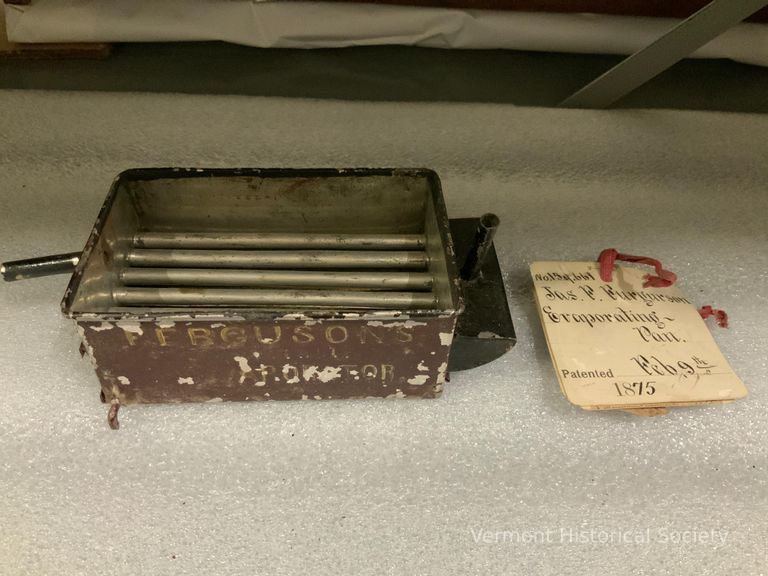
Evaporating pan for "Saccharine Liquids" composed of series of flues passing through from end to end and joined into single flue for smoke escape. Pan should connect to firebox & evaporator (not with model) where boiling and sugaring off occure. "Furguson's Evaporator"
Pan is 4.5 x 3", overall 7: x 3"
Tag verifies this as Patent No. 159,661, by James F. Ferguson of Essex, Vt. registered Feb. 9, 1875. Registration papers in file.
Pan is 4.5 x 3", overall 7: x 3"
Tag verifies this as Patent No. 159,661, by James F. Ferguson of Essex, Vt. registered Feb. 9, 1875. Registration papers in file.
Acquisition
Accession
1978.6
Made/Created
Date made
1875
Dimensions
Entry/Object ID
1978.6.4
Patent Model
Name/Title
Patent Model
Lexicon
Description
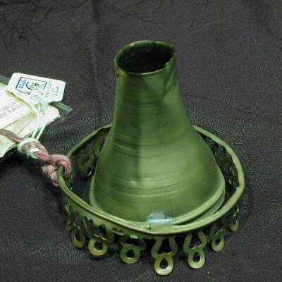
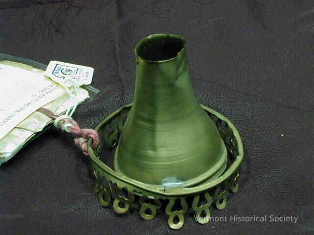
Lamp chimney patent model. The chimney is a metal cylinder that flares as it gets closer to the base. A metal skirting around the chimney’s base has a pierced decorative border and is mostly detached from the chimney. The adjoining tag states, “No. 146, 862 / W.S. Blaisdell / & C.K. Young / Lamp Chimney / Patented Jan. 27th / 1874.” in typed and handwritten text.
Acquisition
Accession
1978.6
Relationships
Related Places
Place
Manchester
Town
Bennington County
County
Vermont
State/Province
United States of America
Country
North America
Made/Created
Date made
1874
Dimensions
Entry/Object ID
1978.6.5
Patent Model
Name/Title
Patent Model
Lexicon
Description
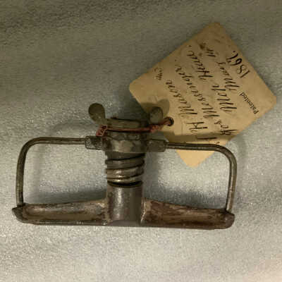
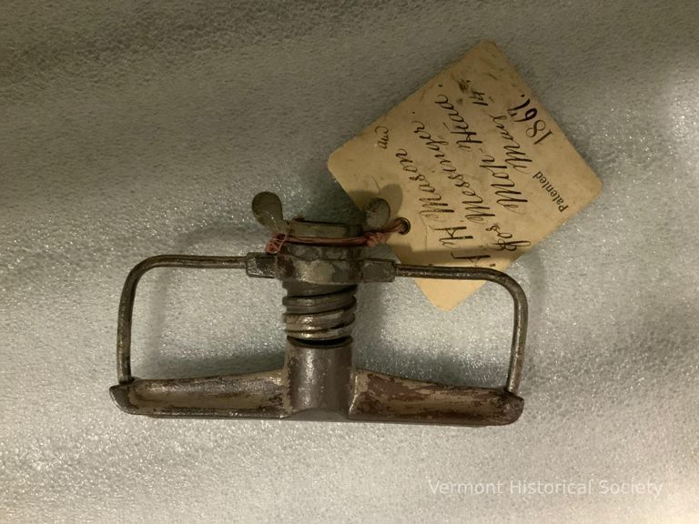
Patent model - mop head. Iron frame composed of screw at top to attach to mop handle, which when tightened closes a shaped bar down onto a heavy wire rim. Rags or other materials would be tightened into place by this screw action. Accompanying tag verifies this as Patent No. 64,683 registered by H.H. Mason and Jos. Messinger of Springfield, VT on May 14, 1867. See Gifts and Loans for papers.
Acquisition
Accession
1978.7
Made/Created
Date made
1867
Dimensions
Materials
Material
Iron, Metal
Entry/Object ID
1978.7
Patent Model
Name/Title
Patent Model
Lexicon
Description
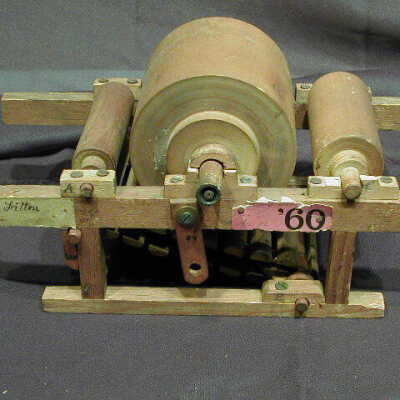
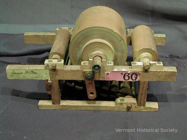
Carding machine patent model. The model has three wooden rollers with different diameters connected to a wood base. Wooden slats nailed to leather straps rests below the rollers and connect to wooden dowels. On the left, “James Fitton” is written in black cursive script on an unstained patch of wood. A red card is nailed to the opposite side of the signature and has torn edges, and reads “Carding machine / Nov. 12 / ‘60” in typed and handwritten script. Different wooden pieces have a cursive letter from A to G.
Wooden model composed of one thick central roller and two smaller rollers on either side. Underneath is a movable belt of wooden slats mounted on two leather straps. Red paper tag - '760'
Tag shows: "No. 30.--5, 1860, J. Fitton, Carding-Engine, Patented Dec. 11th, 1860" and written in hand "Carding/Feeding". "James Fitton" handwritten in ink on wood.
Acquisition
Accession
1978.22
Made/Created
Artist Information
Fitton, James (1819-1890)
Artist
Date made
1860
Dimensions
Entry/Object ID
1978.22.1
Patent Model
Interpretative Labels
Label
Patent Model, 1868
Benjamin F. Wheeler
Calais, Vermont
Wood, metal
Gift of Myrtie B. Wheeler, 1966.19.1
The United States Patent and Trademark Office required inventors to submit a patent model for their designs from 1790 – 1880. Models could be no larger than 12” in any direction. The requirement was a way to make the patent process accessible to homegrown inventors who might not have the drafting or engineering expertise necessary to submit a full, formal patent application. Inventors can still submit a patent model today, particularly in situations where a working model would provide better evidence of their design than the patent application itself. Thanks to several fires at the patent offices in Washington, D.C., many patent models have been lost over the years; others were dispersed in subsequent sales. The Vermont Historical Society possesses a number of patent models related to Vermont inventions.
This patent model showing a new design for carriage brakes was submitted by Benjamin Wheeler. We don’t know much about him other than he primarily worked as a farmer, and submitted this and one patent for a carriage braking system, also in the VHS collections (1966.19.1).
Name/Title
Patent Model
Lexicon
Description
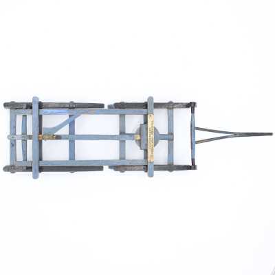
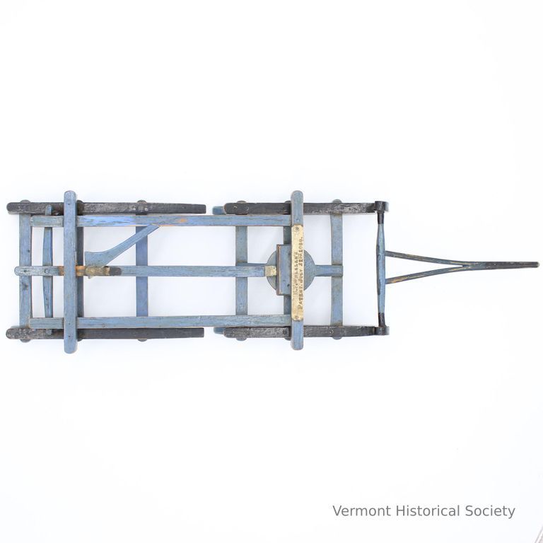
Patent model of a new system for sleigh brakes.
The model is of the chassis system of a sleigh only, constructed from metal and wood. The wood is painted blue. The sleigh rails are in two pieces, and the chassis can pivot at the center. The braking system can be activated from the middle of the chassis, and drops a metal hook down from the rear of the chassis to drag into the snow.
On a strip of wood at the front of the chassis is a small metal plaque with the inscription “B.F. WHEELER’S / PATENT JULY 21ST 1868”
Acquisition
Accession
1966.19
Made/Created
Artist Information
Wheeler, Benjamin F.
Artist
Date made
1868
Dimensions
Dimension Description
Overall
Materials
Material
Wood, Metal
Entry/Object ID
1966.19.1
Context
Made by Benjamin F. Wheeler of Calais, Vermont
Label from an exhibit says, "The brakes were constructed so that as the horses slowed, they applied a stopping force equal to the forward pressure of the load. If the driver wanted to back up, the brakes could easily be readjusted."
Label from an exhibit says, "The brakes were constructed so that as the horses slowed, they applied a stopping force equal to the forward pressure of the load. If the driver wanted to back up, the brakes could easily be readjusted."
Patent Model
Interpretative Labels
Label
Patent Model
Benjamin F. Wheeler
Calais, Vermont
Wood, metal
Gift of Myrtie B. Wheeler, 1966.19.2ab
The United States Patent and Trademark Office required inventors to submit a patent model for their designs from 1790 – 1880. Models could be no larger than 12” in any direction. The requirement was a way to make the patent process accessible to homegrown inventors who might not have the drafting or engineering expertise necessary to submit a full, formal patent application. Inventors can still submit a patent model today, particularly in situations where a working model would provide better evidence of their design than the patent application itself. Thanks to several fires at the patent offices in Washington, D.C., many patent models have been lost over the years; others were dispersed in subsequent sales. The Vermont Historical Society possesses a number of patent models related to Vermont inventions.
This patent model showing a new design for carriage brakes was submitted by Benjamin Wheeler. We don’t know much about him other than he primarily worked as a farmer, and submitted this and one patent for a sleigh braking system, also in the VHS collections (1966.19.1).
Name/Title
Patent Model
Lexicon
Description
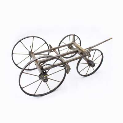
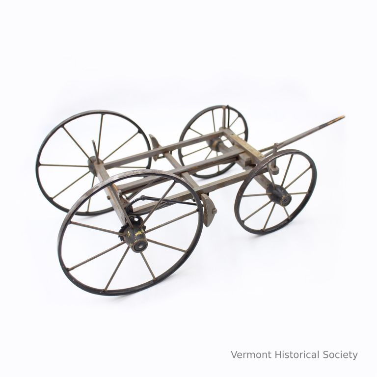
Patent model of a new system for carriage brakes.
The model is just the chassis and wheels of the carriage, in two pieces. The pieces are held together through a pin that connects the front axle to the body of the chassis.
The whole chassis is made of wood and metal, with four wheels, the front pair smaller than the rear. The braking system is activated when the carriage rolls backward, or by a hand brake that is connected to a lever at the left front of the chassis.
The brakes themselves are in front of the rear carriage wheels, held in place by a strip going horizontally across the width of the chassis. When the lever is activated, the wood strip slides backwards and engages the brakes.
Acquisition
Accession
1966.19
Made/Created
Artist Information
Wheeler, Benjamin F.
Artist
Date made
1868
Dimensions
Dimension Description
Overall
Materials
Material
Wood, Metal
Entry/Object ID
1966.19.2a-b
Context
Made by Benjamin F. Wheeler of Calais, VT
From a label in an exhibit: "The self-acting brake no longer stopped forward motion, but prevented a wagon from rolling backward when it was ascending a hill."
From a label in an exhibit: "The self-acting brake no longer stopped forward motion, but prevented a wagon from rolling backward when it was ascending a hill."

Product Model
Name/Title
Product Model
Lexicon
Description
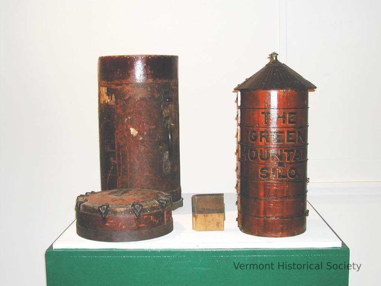
A salesman's model of a silo with its carrying case. The miniature silo is made of red stained wood with a wooden roof. The side of the model is painted with the label, "THE GREEN MOUNTAIN SILO". The inside of the model has a sticker with the inscription, "MANNING MANUFACTURING CO./MANUFACTURERS OF DAIRY & CREAMERY APPARATUS/RUTLAND, VERMONT". The roof comes off the model to show the inside and has a wedge-shaped opening secured with strap hinges. Each level up the side of the silo has a functioning, removable square door. The sample kit comes with two silo board samples. The leather carrying case is shaped to fit the model, with a tightly-fitted removable lid, and a carrying handle on the side.
Use
Used as an example by traveling salespeople in order to sell full-sized silos.
Acquisition
Accession
1994.31
Made/Created
Date made
1900-1914
Manufacturer
Manning Manufacturing Company
Dimensions
Dimension Description
Overall
Materials
Material
Metal
Entry/Object ID
1994.31a-d
Context
Made in Rutland, VT by Manning Manufacturing Company.
Product Model
Interpretative Labels
Label
Portable Voting Booth Product Model, 1911
Made by David Mayo (1847 – 1934)
Montpelier, VT
Wood, metal, leather, fabric
Gift of Earl Templeton, 1983.10.11a-c
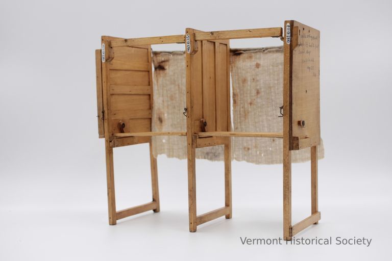
Vermont has long been proud of its democratic traditions, from Town Meeting Day debates to strong participation in local government. Much of our polling takes place in multi-use locations – school gymnasiums, church basements, grange halls, and other community gathering spaces. With this in mind, David Mayo’s design for a portable voting booth that could be folded up and stored flat when not in use made a lot of sense.
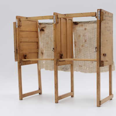
Each modular booth attaches to the next in line, forming a bank of booths to fit any space. The writing platform folds down and faces a wall, and a curtain hangs at the back to preserve privacy. This model was constructed at the scale of 1 ½ inches to 1 foot. A fully constructed voting booth in this style would stand just over 6 feet tall.
In 1911, Mayo developed this device specifically for use in Montpelier City Hall’s large auditorium, a multi-use space that required free-standing furniture without the use of floor or wall anchors. He used this small product model to demonstrate his system to Montpelier residents and City Council. On January 16, 1912, Montpelier City Council voted to acquire 66 panels of Mayo’s design, which would join to make 60 booths. The total cost for production was $287.75, or about $8,300 today. Unfortunately, none of the full-scale booths have survived to the present day.
David Mayo was born in Chazy, New York, and came to Montpelier in the 1870s to apprentice as a wheelwright. He worked as a wheelwright, carriage maker, and general handyman for 47 years and retired to live with his daughter in Newport, Vermont, in 1914. He passed away in 1934. He constructed a number of small scale models that are today in the collections of the Vermont Historical Society. He does not seem to have applied for patents for any of them.
Name/Title
Product Model
Lexicon
Description
Scale model of portable election booths. The model consists of three panels and two curtains. Each panel consists of two legs connected by a stretcher, solid upper halves, an upper stretcher connected with a leather hinged, and a table connected with a leather hinge. The panels connect together via the tables and upper stretchers. The curtains are blue and white cotton with a wire rod across the top. The rod is inserted to eye rings for hanging between the panels.
One panel is inked with the label, "portable voting Booth / Scale 1 1/2 inch to foot / David Mayo / Montpelier Vt / May 22 / 1911". Another panel is inked with the label, "Portable voting & folding Booth."
One panel is inked with the label, "portable voting Booth / Scale 1 1/2 inch to foot / David Mayo / Montpelier Vt / May 22 / 1911". Another panel is inked with the label, "Portable voting & folding Booth."
Acquisition
Accession
1983.10
Made/Created
Artist Information
Mayo, David (1847-1934)
Artist
Date made
1911
Dimensions
Dimension Description
Overall
Entry/Object ID
1983.10.11a-e
Context
Developed by David Mayo as a model for a portable system of election booths to be used at Montpelier City Hall
From an exhibit label:
"David Mayo was born in 1847 or 1848 in Chazy, New York. He moved to Montpelier in 1867 to apprentice as a wheelwright in the carriage-making shop of H.N. Taplin. Several of the inventors in this exhibit were wheelwrights, or wheel makers. They learned how to work with both wood and metal, two materials essential to most inventions of the time.
Mayo opened his own shop on Elm Street in 1871 and remained there for 42 years. He is a prime example of the ingenious Yankee, and his many models and drawings show his solutions to his customers' needs. When Mayo retired, the local newspaper reported on "the many models of things manufactured by him such as dump carts and sleds, snow scrapers, potato planters and potato hoes, hay wagons, sheep rack and snow roller, also election booths." To our knowledge, Mayo never patented any of his creations."
Prosthesis
Name/Title
Prosthesis
Lexicon
Description
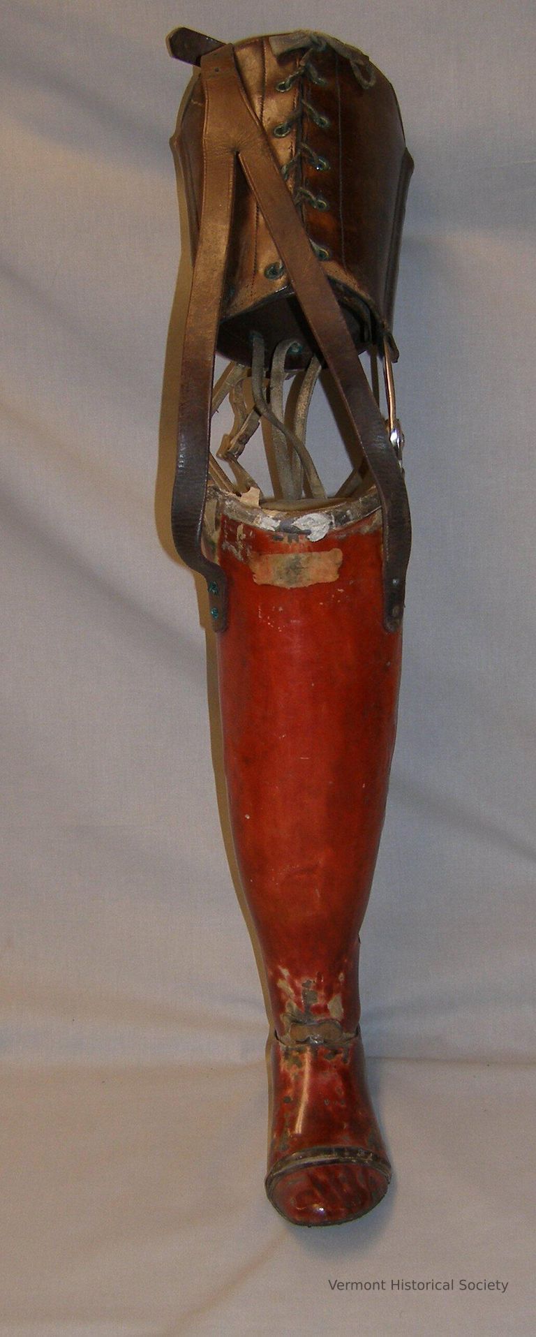
Right leg prosthesis. The top of the prosthesis has a leather cuff for the thigh with a leather lace threaded through grommets running down the front of the cuff. A similar piece of lace is threaded on the back of the cuff. The words “J.E. HANGER / WASH’N, D.C.” are imprinted on the leather. Two metal hinges connect the leather and the composite material of the calf. Six leather laces connect behind these metal hinges The calf section is hollow with scraps of cloth at the top. The calf section is a red color with obvious wear around the ankle and feet, and replicates the natural curves of a calf or a booted foot. A large circular hole is carved out of the outside above the ankle. A long leather loop is attached to the front to connect with a garter.
Use
Owned by James M. Ewen of Barre in the 1920s.
Acquisition
Accession
2013.35
Relationships
Related Person or Organization
Ewen, James M. (1879-1927)
Person or Organization
Made/Created
Manufacturer
J. E. Hanger
Dimensions
Materials
Material
Leather, Metal, Composition
Entry/Object ID
2013.35.2
Radio
Name/Title
Radio
Lexicon
Description
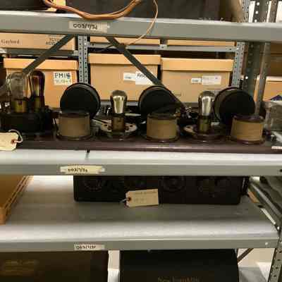
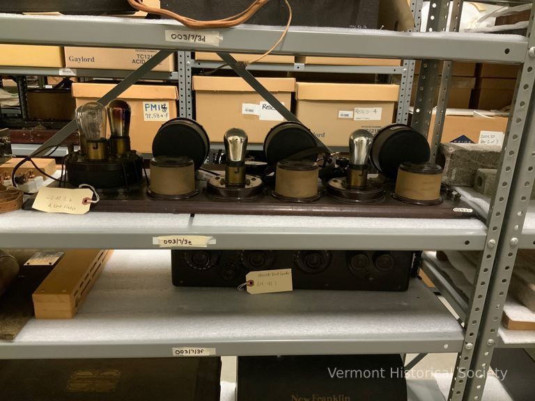
Atwater Kent radio, 1923 type 5a, and headphones. The radio consists of a wooden board with beveled edges. On the surface, six different size cylindrical pieces are attached to a rectangular wooden slab with a concave curved trim. From the left, the largest cylinder has about six knobs attached to rubber covered wires that connect with the wooden slab. Three lightbulbs with chrome-like globes extend from the top and are showing some blackening inside the bulb. The metal label has a red circle in the center with gold lettering that says “AK” with “MADE IN THE U.S.A.” below the circle. The label reads, “ATWATER KENT / PHILA. TYPE TA / PATENTS PENDING / DETECTOR AND 2 STAGE A.F. AMPLIFIER. The next four cylinders alternate between a tall cylinder and squat cylinders with a silver painted light bulb attached. Three dials read 100 to 0 from left to right. The metal headphones connect to the largest cylinder and reads “FROST FONES / NO. 163 / 1500” on the speakers.
a=003/7/3d
b=003/7/3e
a=003/7/3d
b=003/7/3e
Acquisition
Accession
1962.42
Relationships
Related Person or Organization
Kent, Arthur Atwater (1873-1949)
Person or Organization
Made/Created
Date made
1923
Dimensions
Entry/Object ID
1962.42.2b
Steam Engine
Interpretative Labels
Label
Steam Engine, ca. 1793
Samuel Morey
Fairlee, Vermont
Tin, brass
Gift of Amelia S. Morey Kibbey, 1900.2
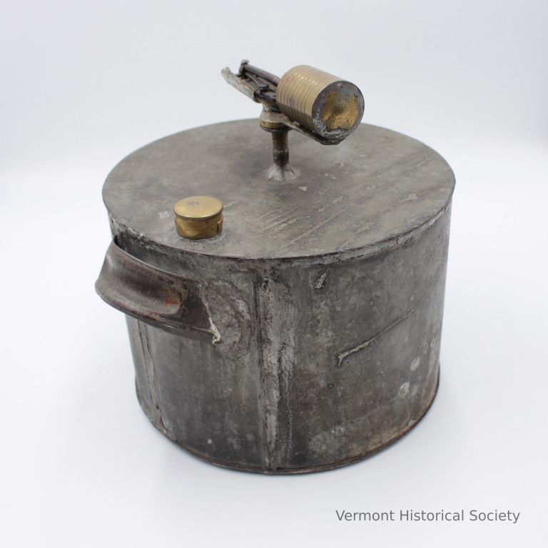
Samuel Morey was an inventor from Fairlee, Vermont and Orford, New Hampshire. He first began experimenting with steam power in the 1780s, and his first patent, in 1793, was for a steam-powered spit (for cooking food). In the early 1790s, he began to develop a steam engine that he ultimately used to power a small boat that he drove up and down the Connecticut River. Legend has it that he snuck out to test his craft early on a Sunday morning, while the rest of the town was at church, so that he would be spared embarrassment in case of failure.
Morey continued to develop his ideas for steam-powered boats, but he was slow to patent them, and in the early 19th century Robert Fulton and Robert Livingston joined together to create the first steamship line in America. They have typically received credit for creating workable steam engines, though Morey disputed their claims and argued that they stole his ideas.
Morey continued to invent throughout his life, and in the 1820s he invented and attempted to sell an early internal combustion engine. He failed to attract buyers, but beginning in the 1890s, many automobile inventors credited his work as an inspiration.
This model of Morey’s original steam engine comes from the Morey family, and is one of the longest-tenured objects in our collections.
Name/Title
Steam Engine
Lexicon
Description
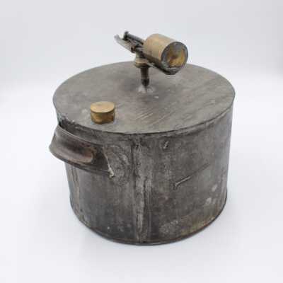
Steam engine patent model. A tin cylinder with soldered edges, closed off on all sides, with two concave metal handles creates the majority of the model. The drum has two openings: the steam outlet and a brass feed opening. The steam outlet ends in a t-shape that balances a rotating piston and rods.
Acquisition
Accession
1900.2
Relationships
Related Person or Organization
Morey, Samuel (1762-1843)
Person or Organization
Related Places
Place
Bradford
Town
Orange County
County
Vermont
State/Province
United States of America
Country
North America
Made/Created
Artist Information
Morey, Samuel (1762-1843)
Artist
Date made
circa 1793
Dimensions
Dimension Description
Overall
Materials
Material
Tin, Brass
Entry/Object ID
1900.2
Context
Invented by Samuel Morey of Fairlee, who used it to power a small boat, this was one of the earliest working piston steam engines in America.
Web Links and URLs
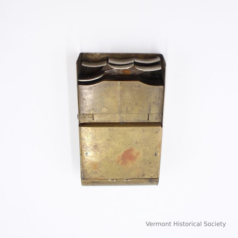
Typewriter
Interpretative Labels
Label
Permutation Typograph, ca. 1857
Benjamin Livermore
Harland, VT
Brass, steel
Transfer from Hartland Historical Society, 1982.6.1
Benjamin Livermore’s “Permutation Typograph” is a kind of early typewriter. He was far from the first to develop a machine for writing; many others had been experimenting with and tweaking mechanical devices for typing for decades before him.
Livermore, who lived in Hartland, patented his device and advertised it via pamphlets and public demonstrations. It’s not clear how widely it was produced. His innovation was in slimming down the device into something he could – and did – operate out of his own pocket. The six keys on the device could be used singly or in combination to select a letter or symbol, and could then type out notes in a kind of shorthand. The case held both type keys and a scroll of paper.
A family member recalled that he used the device personally: “He would print with it in the dark. He usually carried it in his pocket and could print it there, placing his hand in such a position that his fingers rested on the keys. After taking down the conversation of those he met, he placed it under his pillow at night to catch any stray thoughts, as he termed it.”
Livermore’s device, while not necessarily crucial in the larger story of printing, is a fascinating and highly personal story within that history. Livermore was a prolific inventor who also patented a machine for forming cement pipes and a boot crimper.
Name/Title
Typewriter
Lexicon
Description
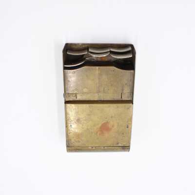
Early typograph, or typewriter. Small rectangular metal box with six convex keys at one end in two rows, three to a row. The other end of the box is curved. The lid of the box opens to reveal an internal printing mechanism, with a roller for paper, printing keys, and levers. The device is broken and many of the internal components are loose; it’s not clear precisely how they would have fit together.
Acquisition
Accession
1982.6
Made/Created
Artist Information
Livermore, Benjamin
Artist
Date made
circa 1857
Dimensions
Dimension Description
Overall
Materials
Material
Brass, Steel
Entry/Object ID
1982.6.1
Context
Made and used by Benjamin Livermore of Hartland, VT.